RISC-V Is Getting MSIs!
Contents
- Overview
- Repository
- Message Signaled Interrupts (MSI)
- Incoming MSI Controller (IMSIC)
- Conclusion
- What’s Next
Overview
Message signaled interrupts or MSIs describe a way to signal an interrupt without a dedicated interrupt request pin (IRQ). One of the most prevalent uses for MSIs is the PCI bus, and the PCI specification defines the MSI and MSI-X standards. The potential benefits may include: (1) reduced number of direct wires from the device to the CPU or interrupt controller, (2) improve signaling performance–mainly by forcing in-band signals by design, and (3) improving guest/host signaling for virtualized environments.
Wikipedia’s article on MSIs can be found here: https://en.wikipedia.org/wiki/Message_Signaled_Interrupts
Repository
All of the code for this post can be found here: https://github.com/sgmarz/riscv_msi. Use tag “msi”.
The code is written for RV32I in Rust. I originally wrote it for RV64GC, but everything else I wrote is also for RV64GC, so I figured I should branch out and broaden my horizons.
The AIA draft manual, written by John Hauser, can be found here: https://github.com/riscv/riscv-aia. This blog post uses version 0.3.0-draft.31, tagged on 13-Jun-2022.
Message Signaled Interrupts (MSI)
An MSI is triggered by a “message”, which is a fancy term for a “memory write”. In fact, we can trigger a message by simply dereferencing an MMIO pointer.
// Note that 0xdeadbeef is not really a valid message.
// The AIA specifies messages 1 through 2047 are valid due to the number of registers
// available. But, the following is just an example.
let message = 0xdeadbeef;
// QEMU's 'virt' machine attaches the M-mode IMSIC for HART 0 to 0x2400_0000
// The AIA specifies that this must be a word, a double word will cause a trap.
write_volatile(0x2400_0000 as *mut u32, message);
Memory Mapped IO Addresses for Interrupt Files
The code above writes to the MMIO address 0x2400_0000, which is where QEMU’s virt machine connects the M-mode IMSIC for HART 0. The S-mode IMSIC for HART 0 is connected to 0x2800_0000. Each HART is a page away from each other, meaning the M-mode IMSIC for HART 1 is at 0x2400_1000, and the S-mode IMSIC for HART 1 is 0x2800_1000.
For many embedded systems, these values would come from a specification or from an open firmware (OF) package that contained a flattened device tree (FDT) that specifies an MMIO address and what’s connected to it. Here’s an example of QEMU’s virt FDT as plain text. For the repo, I hard coded the MMIO addresses instead of reading a device tree.
imsics@24000000 {
   phandle = <0x09>;
   riscv,ipi-id = <0x01>;
   riscv,num-ids = <0xff>;
   reg = <0x00 0x24000000 0x00 0x4000>;
   interrupts-extended = <0x08 0x0b 0x06 0x0b 0x04 0x0b 0x02 0x0b>;
   msi-controller;
   interrupt-controller;
   compatible = "riscv,imsics";
};
The organization that standardizes device tree formats can be found here: https://www.devicetree.org/
More information about device trees in Linux can be found here: https://www.kernel.org/doc/html/latest/devicetree/usage-model.html
IMSICs were added to QEMU’s virt machine fairly recently, so you may need to clone and build your own QEMU. QEMU’s repository can be found here: https://github.com/qemu.
Triggering an Interrupt by Sending a Message
After a device writes a word to a specific MMIO address, the interrupt is triggered. This means that devices do not need a wire connecting it to an IRQ controller, such as RISC-V’s platform-level interrupt controller, or PLIC. Instead, as long as the device can make a memory write, it can trigger an interrupt.
Even though triggering a message is that simple, we need a mechanism to enable and prioritize these messages. There might be some circumstances where we don’t want to hear certain messages. This is where the incoming MSI controller or IMSIC comes into play.
Incoming MSI Controller (IMSIC)
To be able to support MSIs, some device needs to be able to take memory writes and turn them into interrupts. Furthermore, the device needs to provide a mechanism to enable/disable and to prioritize interrupts just like a regular interrupt controller. This is done by the incoming MSI controller (IMSIC) device.
WARNING: The Advanced Interrupt Architecture (AIA) manual is still a work-in-progress, and already, there have been major changes that removed or added CSRs or other pertinent information. So, some of the code and tables might be outdated.
The register mechanism for the IMSIC consists of several control and status registers (CSRs) as well as internal registers accessibly through a selection mechanism.
Newly Added Registers
The AIA defines several new CSRs separated between the machine and supervisor modes.
| Register Name | Register Number | Description |
|---|---|---|
| MISELECT | 0x350 | Machine register select |
| SISELECT | 0x150 | Supervisor register select |
| MIREG | 0x351 | A R/W view of the selected register in MISELECT |
| SIREG | 0x151 | A R/W view of the selected register in SISELECT |
| MTOPI | 0xFB0 | Machine top-level interrupt |
| STOPI | 0xDB0 | Supervisor top-level interrupt |
| MTOPEI | 0x35C | Machine top-level external interrupt (requires IMSIC) |
| STOPEI | 0x15C | Supervisor top-level external interrupt (requires IMSIC) |
The registers MISELECT and MIREG allow us to select a register by writing its number into the MISELECT register. Then the MIREG will represent the selected register. For example, if we read from MIREG, we read from the selected register, and if we write to MIREG, we write to the selected register.
There are four selectable registers. There are machine and supervisor versions of these registers. For example, if we write to SISELECT, we will view the supervisor version of the register.
| Register Name | MISELECT/SISELECT | Description |
|---|---|---|
| EIDELIVERY | 0x70 | External Interrupt Delivery Register |
| EITHRESHOLD | 0x72 | External Interrupt Threshold Register |
| EIP0 through EIP63 | 0x80 through 0xBF | External Interrupt Pending Registers |
| EIE0 through EIE63 | 0xC0 through 0xFF | External Interrupt Enable Registers |
The first thing we need to do is enable the IMSIC itself. This is done through a register called EIDELIVERY for “enable interrupt delivery” register. This register may contain one of three values:
| Value | Description |
|---|---|
| 0 | Interrupt delivery is disabled |
| 1 | Interrupt delivery is enabled |
| 0x4000_0000 | Optional interrupt delivery via a PLIC or APLIC |
Enabling the IMSIC
So, we need to write 1 (Interrupt delivery is enabled) into the EIDELIVERY register:
// First, enable the interrupt file
// 0 = disabled
// 1 = enabled
// 0x4000_0000 = use PLIC instead
imsic_write(MISELECT, EIDELIVERY);
imsic_write(MIREG, 1);
The EITHRESHOLD register creates a threshold that interrupt priorities must be before it can be heard. If an interrupt has a priority less than the value in EITHRESHOLD, it will be “heard” or unmasked. Otherwise, it will be masked and will not be heard. For example, an EITHRESHOLD of 5 would only permit messages 1, 2, 3, and 4 to be heard. The message 0 is reserved to mean “no message”.
Since a higher threshold opens more messages, messages with a lower number have a higher priority.
// Set the interrupt threshold.
// 0 = enable all interrupts
// P = enable < P only
imsic_write(MISELECT, EITHRESHOLD);
// Only hear 1, 2, 3, and 4
imsic_write(MIREG, 5);
Interrupt Priorities
The AIA documentation uses the message itself as the priority. So, a message of 1 has a priority of 1, whereas a message of 1234 has a priority of 1234. This is more convenient since we can control messages directly. However, since each message number has associated enable and pending bits, there is a limit to the highest numbered interrupt. The specification has a maximum of \(32\times64 – 1 = 2,047\) total messages (we subtract one to remove 0 as a valid message).
Enabling Messages
The EIE register controls whether a message is enabled or disabled. For RV64, these registers are 64-bits wide, but still take up two adjacent register numbers. So, for RV64, only even numbered registers are selectable (e.g., EIE0, EIE2, EIE4, …, EIE62). If you try to select an odd numbered EIE, you will get an invalid instruction trap. This took me many hours to figure out even though the documentation states this is the desired behavior. For RV32, the EIE registers are only 32-bits, and EIE0 through EIE63 are all selectable.
The EIE register is a bitset. If the bit for a corresponding message is 1, then it is unmasked and enabled, otherwise it is masked and is disabled. For RV64, messages 0 through 63 are all in EIE0[63:0]. The bit is the message. We can use the following formulas to determine which register to select for RV64:
// Enable a message number for machine mode (RV64)
fn imsic_m_enable(which: usize) {
    let eiebyte = EIE0 + 2 * which / 64;
    let bit = which % 64;

    imsic_write(MISELECT, eiebyte);
    let reg = imsic_read(MIREG);
    imsic_write(MIREG, reg | 1 << bit);
}
RV32 behaves much the same, except we don’t have to scale it by 2.
// Enable a message number for machine mode (RV32)
fn imsic_m_enable(which: usize) {
    let eiebyte = EIE0 + which / 32;
    let bit = which % 32;

    imsic_write(MISELECT, eiebyte);
    let reg = imsic_read(MIREG);
    imsic_write(MIREG, reg | 1 << bit);
}
With the code above, we can now enable the messages we want to hear. The following example enables messages 2, 4, and 10.
imsic_m_enable(2);
imsic_m_enable(4);
imsic_m_enable(10);
Pending Messages
The EIP registers behave in the exact same way as the EIE registers except that a bit of 1 means that that particular message is pending, meaning a write to the IMSIC with that message number was sent. The EIP register is read/write. If we read from it, we can determine which messages are pending. If we write to it, we can manually trigger an interrupt message by writing a 1 to the corresponding message bit.
// Trigger a message by writing to EIP for Machine mode in RV64
fn imsic_m_trigger(which: usize) {
    let eipbyte = EIP0 + 2 * which / 64;
    let bit = which % 64;

    imsic_write(MISELECT, eipbyte);
    let reg = imsic_read(MIREG);
    imsic_write(MIREG, reg | 1 << bit);
}
Testing
Now that we can enable the delivery as well as indiviual messages, we can trigger them one of two ways: (1) write the message directly to the MMIO address or (2) set the interrupt pending bit of the corresponding message to 1.
unsafe {
    // We are required to write only 32 bits.
    // Write the message directly to MMIO to trigger
    write_volatile(0x2400_0000 as *mut u32, 2);
}
// Set the EIP bit to trigger
imsic_m_trigger(2);
Message Traps
Whenever an unmasked message is sent to an enabled IMSIC, it will come to the specified HART as an external interrupt. For the machine-mode IMSIC, this will come as asynchronous cause 11, and for the supervisor-mode IMSIC, this will come as asynchronous cause 9.
When we receive an interrupt due to a message being delivered, we will need to “pop” off the top level pending interrupt by reading from the MTOPEI or STOPEI registers depending on the privilege mode. This will give us a value where bits 26:16 contain the message number and bits 10:0 contain the interrupt priority. Yes, the message number and message priority are the same number, so we can choose either.
// Pop the top pending message
fn imsic_m_pop() -> u32 {
    let ret: u32;
    unsafe {
        // 0x35C is the MTOPEI CSR.
        asm!("csrrw {retval}, 0x35C, zero", retval = out(reg) ret),
    }
    // Message number starts at bit 16
    ret >> 16
}
My compiler does not support the names of the CSRs in this specification, so I used the CSR number instead. That is why you see 0x35C instead of mtopei, but they mean the same thing.
When we read from the MTOPEI register (0x35C), it will give us the message number of the highest priority message. The instruction csrrw in the code snippet above will atomically read the value of the CSR into the return register and then store the value zero into the CSR.
When we write zero into the MTOPEI register (0x35C), we are telling the IMSIC that we are “claiming” that we are handling the topmost message, which clears the EIP bit for the corresponding message number.
/// Handle an IMSIC trap. Called from `trap::rust_trap`
pub fn imsic_m_handle() {
    let msgnum = imsic_m_pop();
    match msgnum {
        0 => println!("Spurious message (MTOPEI returned 0)"),
        2 => println!("First test triggered by MMIO write successful!"),
        4 => println!("Second test triggered by EIP successful!"),
        _ => println!("Unknown msi #{}", v),
    }
}
Message 0 is not a valid message since when we pop from the MTOPEI, a 0 signals “no interrupt”.
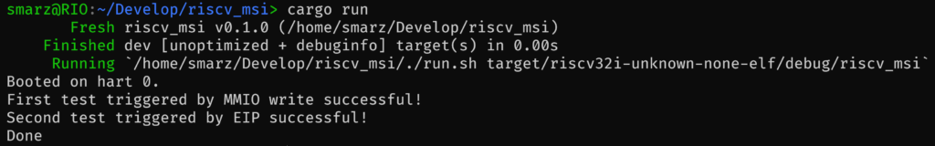
Example Output
If you run the repo with a new QEMU, you should see the following after a successful test.
Conclusion
In this post, we saw the new registers added to support the incoming MSI controller (IMSIC) for RISC-V. We also enabled the IMSIC delivery, the individual messages, and handled two ways of sending a message: via MMIO directly or by setting the corresponding EIP bit. Finally, we handled the interrupt from the trap.
What’s Next?
The second part of the AIA manual includes the new Advanced Platform-Level Interrupt Controller or APLIC. We will examine this system as well as write drivers to start looking at how this new APLIC can signal using wires or messages.
After the APLIC, we will write a driver for a PCI device and use it to send MSI-X messages.