My original OS Blog (see here: https://osblog.stephenmarz.com) ran the operating system in RISC-V’s machine mode, which is the most privileged mode in the RISC-V architecture. It has access to all control and status registers, runs in physical memory only, and has no restrictions placed upon it by the CPU.
I recently ran across the OpenSBI (Open Supervisor Binary Interface), listed on Github here: https://github.com/riscv/opensbi. It’s been around a little while, but it seeks to be an interface between the operating system and the machine–the low-level system.
Currently, OpenSBI has a legacy interface that abstracts the UART device for you, as well as a HART (hardware thread–RISC-V’s name for a CPU core) management system–start a hart at a given address, stop a hart, get the status of a hart, etc.
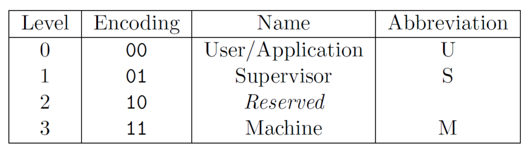
The supervisor mode, known as S mode in RISC-V, is two layers below Machine mode, as shown in the RISC-V specification below. This means that our operating system uses the OpenSBI set of utilities for very low level things, in which the OpenSBI abstracts away. This makes designing an operating system for the myriad of boards a bit easier.
RISC-V Privilege Levels
Why Supervisor Mode?
Why run the operating system at S mode? Well, whereas a high-level language as the application binary interface, or ABI, the operating system can rely on a certain set of utilities given by a RISC-V “bios” for a lack of a better term.
This allows our operating system to abstract much of the machine architecture away. Instead of relying on the actual system’s specification, we can program the operating system using more or less the RISC-V specification only.
To understand what’s going on, let’s take a look at the user level. This is where applications live. Whenever a user application runs afoul of the “rules”, such as dereferencing an invalid memory location or executing an illegal instruction, the CPU will trap to the machine mode, unless the trap is delegated lower. Luckily for us, OpenSBI delegates user traps to the supervisor mode, so our operating system can handle it.
Now, let’s move up one level. What happens when the operating system runs afoul of the rules? In most respects, the system crashes. An illegal instruction in machine mode will trap into machine mode. This can potentially cause a loop of traps in machine mode, as one compounds another.
So, as U-mode is to S-mode, S-mode is to M-mode, meaning that if the operating system runs at S-mode and messes with the CPU, then the OpenSBI will handle the trap. Usually, this means trying to load the hart into a stable, known state.
Complications while in Supervisor Mode
I wrote my operating system in machine mode to make it easier to understand the RISC-V architecture. Now, switching to S-mode has complicated some things. One of the major issues I have found is that the hart’s unique id is in the mhartid register. That little m in front of it means that it is a machine-mode register. Since we’re at a lower level, we’re not allowed to access any of the machine mode registers. If we try, we will get an illegal instruction.
This means that we have to keep track of our own core id. This makes context switching and putting applications on a different core slightly more complicated. We can’t just read the mhartid register and know our hart id. Instead, we have to follow the OpenSBI interface. This is easier said than done!
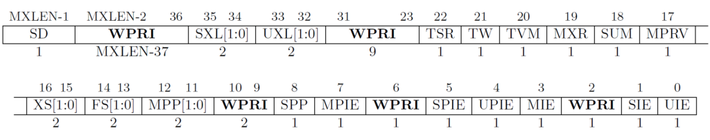
Now that we don’t have access to any of the machine mode registers, we have to use the supervisor levels. Luckily, RISC-V gives us “views” of the same register with an s in front of it. For example, mstatus becomes sstatus. The neat thing is that if we write to sstatus, the machine-only bits are masked, and we can only set the supervisor bits. This means we can’t switch ourselves into machine mode while in supervisor mode by simply setting the mstatus bits (bits 12 and 11).
Machine Status Register Bits
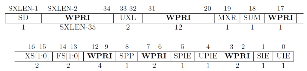
The sstatus register is the exact same register as the mstatus register, but when we make writes to it, the CPU will not change any machine-only bits. This is called a “view” of the machine status register. Here’s the supervisor status register. Take note of the machine bits that are masked.
Supervisor Status Register Bits
Notice that bits 12 and 11 (Machine Previous Privilege Mode [MPP]) are WPRI, which stands for Write-Preserve, Read-Ignore. Write-preserve means that if we write to bits 12 and 11, it will preserve their original value, which essentially prevents us from writing to MPP in supervisor mode. Read-ignore means that if we try to read bits 12 and 11, we won’t get the actual data. Instead, it ignores the data and usually will give us 0.
This changes the way we switch from supervisor mode into user mode. So, if we put 1 into SPP (bit 8 of sstatus), then when we execute the sret (supervisor return), then this bit will become the privilege level. Recall that level 1 is supervisor mode. If we put 0 in bit 8, then after an sret, we will be in user mode. Recall that user mode is level 0.
Complications with Interrupts
Interrupts trigger a pin on the CPU to cause a trap. This is usually in response to something, such as a timer, a software interrupt, or an external, platform-level interrupt, such as a keyboard input or wifi notification.
The interrupts I’m concerned about are at the platform level. RISC-V has a specification for the platform-level interrupt controller, or PLIC. In this, we can configure the PLIC to trap in supervisor mode or even in machine mode. Since the PLIC is directly connected to the CPU, we, at supervisor mode, can tell the PLIC where to send interrupts. This makes our job a little bit harder since there are many different configurations of multiple-harts, different hart configurations and so on.
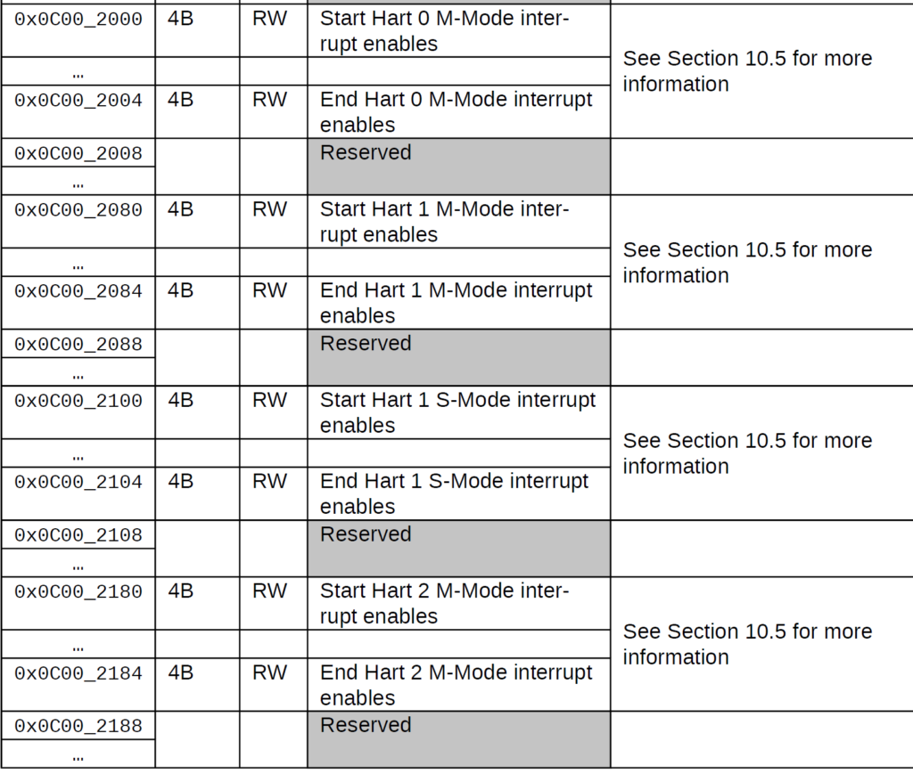
To demonstrate this, here’s the memory map of the PLIC on a 5-hart CPU where the 0-hart only has M mode, and harts 1, 2, 3, and 4 have both M and S mode.
FU540 PLIC Memory Map
As you can see, our stride isn’t the same for every hart, so we will have to configure our operating system nearly at machine-level. If you take a look at the virt cpu in QEMU (see qemu/virt.h at master · qemu/qemu (github.com)). So, I can’t go off of just configuring each hart to enable an interrupt, I have to specify the mode where I want the interrupt to be trapped. Furthermore, each hart is not necessarily the same, as you can see with the diagram above. the FU540 has hart 0 (called the “monitor core”) to supervise the other cores, which runs in machine mode only.
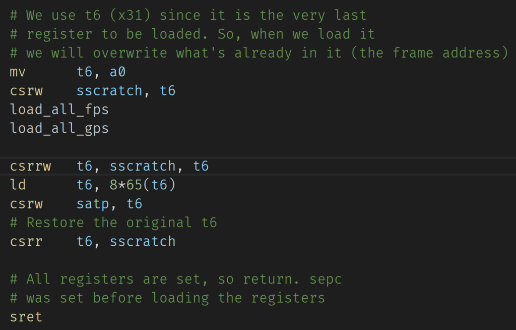
Traps also require us to context switch, by saving the current set of registers into the context running on the hart, scheduling the next context, and loading that context onto the hart. This was fairly simple in machine mode for one reason–the MMU is turned off automatically in machine mode. This is not the case in supervisor mode. Furthermore, the MMU register, called supervisor address translation and protection (SATP), is immediate. Meaning, if I set the mode, the MMU immediately turns on. This can be a problem because I have to juggle certain registers. Take a look at the trap handler written in RISC-V assembly below.
Supervisor Address Translation and Protection Register Handler
(Updated screenshot): I originally had sstatus instead of sscratch. The point of csrrw is to make an atomic swap of sscratch into t6 and the old value of t6 into sscratch. This allows us to keep both values.As a side note, this is actually the second time I’ve done this. My typing fingers just like sstatus better than sscratch.
As you can see, we have to be careful not destroy a register in our context. I usually use the t6 register since it is register number 31, which is the last register for an ascending loop. In the code above, I’m making sure that no memory accesses are made after the SATP register is written to. Remember, it’s immediate. As soon as I write to the SATP register and set the mode, it is up and running since we’re in supervisor mode.
This leads us to a little bit of a problem. Unless we map this handler, it will not be able to execute–and we still need to get to sret. Recall that X (execute) is one of our bits and so is the U (user) bit. So, how do we handle this? We will see in the next post. Stay tuned.
Conclusion
I’m still working on migrating my machine-mode operating system into a supervisor-mode operating system. This is a work in progress, so I encourage you to keep up to date on this blog!
An operating system is used to make our job easier when using graphics. In our instance, in addition to everything else. In this post, we will be writing a GPU (graphics processing unit) driver using the VirtIO specification. In here, we will allow user applications to have a portion of the screen as RAM–with what is commonly known as a framebuffer.
We command the virtual GPU (virtio-gpu) by sending certain commands to the host (the device). The guest (the OS driver) has an allocation of RAM that becomes the framebuffer. The driver then tells the device, “hey, here’s the RAM that we’re going to use to store pixel information.”
The RAM is contiguous in our OS, but according to the specification, this isn’t strictly required. We will give the driver a rectangle. Everything that falls within that rectangle will be copied to the host. We don’t want to keep copying the entire buffer over and over again.
We will be using the virtio protocol that we used for the block driver here, so I won’t rehash the general virtio protocol. However, the device-specific structures are a bit different, so we’ll cover that part more in depth.
Pixels and Resolution
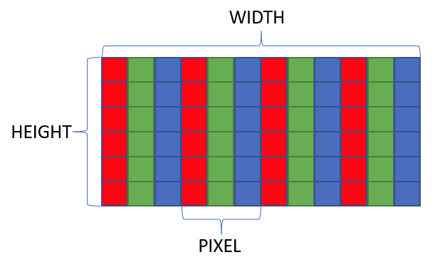
A framebuffer must be large enough to store \(\text{width}\times\text{height}\times\text{pixel size}\) number of bytes. There are \(\text{width}\times\text{height}\) number of pixels. Each pixel has a 1-byte red, green, blue, and alpha channels. So, each pixel is exactly 4 bytes with the configuration we’re going to specify.
The framebuffer for our junior GPU driver is going to support a fixed resolution of \(640\times 480\). If you’re a child of the 90s, you saw this resolution a lot. In fact, my first computer, a Laser Pal 386, had a 16-color monitor with a resolution of 640 pixels wide with 480 pixels tall.
There are red, green, and blue pixels so close together that by varying the intensity of these three channels, we can change the color. The closer we get to our monitors, the easier a pixel is to see.
Pixels on a Viewsonic VX2770SMH-LED monitor.
You can see these little squares. If you squint enough, you can see that they aren’t pure white. Instead, you can see bits of red, blue, and green. That’s because each one of these little squares is subdivided into three colors: yep, red, green, and blue! To make white, these pixels are turned up to 11 (get the joke?). To make black, we turn off all three channels of that pixel.
The resolution refers to how many of these squares are on our monitor. This is a 1920×1080 monitor. That means that there are 1920 of these squares going left to right, and there are 1080 of these squares from top to bottom. All in all, we have \(1920\times 1080=2,073,600\) number of pixels. Each one of these pixels is expressed using 4 bytes in the framebuffer, meaning we need \(2,073,600\times 4=8,294,400\) bytes in RAM to store the pixel information.
You can see why I limited our resolution to 640×480, which only requires \(640\times 480\times 4=1,228,800\) bytes–a bit over a megabyte.
The GPU VirtIO Device
The GPU device requires us to read a more up-to-date VirtIO specification. I’ll be reading from version 1.1, which you can get a copy here: https://docs.oasis-open.org/virtio/virtio/v1.1/virtio-v1.1.html. Specifically, chapter 5.7 “GPU Device”. This is an unaccelerated 2D device, meaning that we must use the CPU to actually form the framebuffer, then we transfer our CPU formulated memory location to the host GPU, which is then responsible for drawing it to the screen.
The device uses a request/response system, where we the driver make a command to request something from the host (the GPU). We add a bit of extra memory into our request so that the host can formulate its response. When the GPU interrupts us, we can take a look at this response memory location to see what the GPU told us. This is much like the status field on the block driver, where the block device tells us the status of our last request.
Each request starts with a Command Header, which in Rust looks as follows:
I took this directly from the specification, but Rust-ified the names to avoid getting yelled at by the linter.
Pixel Formats
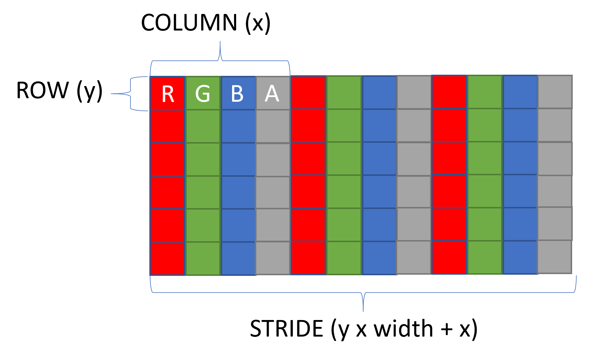
Recall that the framebuffer is just a bunch of bytes in memory. We need to put a structure behind the framebuffer so the host (the GPU) knows how to interpret your sequence of bytes. There are several formats, but all-in-all, they just re-arrange the red, green, blue, and alpha channels. All are exactly 4 bytes, which makes the stride the same. The stride is the spacing from one pixel to another–4 bytes.
The type, unorm, is an 8-bit (1-byte) unsigned value from 0 through 255, where 0 represents no intensity and 255 represents full intensity, and a number in between is a linear-interpolation between no and full intensity. Since there are three color (and one alpha), that gives us \(256\times 256\times 256=16,776,216\) different colors or levels of colors.
For this tutorial, I selected R8G8B8A8Unorm = 67, which has red first, green second, blue third, and alpha fourth. This is a common ordering, so I’ll select it to make it easy to follow along.
Our selected format makes the pixel structure look as follows:
Recall that each individual component R, G, B, and A are each one byte a piece, so each Pixel referred to by (x, y) is 4 bytes. This is why our memory pointer is a Pixel structure instead of a byte.
Initialization
Just like all other virtio devices, we set up the virtqueues first and then we work on device-specific initialization. In my code, I just directly copied-and-pasted from the block driver into the gpu driver. The only thing I added to the Device structure was the framebuffer and dimensions of the framebuffer.
The specification tells us to do the following in order to initialize the device and get things ready to draw. I Rust-ified some of the content to match our enumerations.
Create a framebuffer and configure scanout
Create a host resource using CmdResourceCreate2d.
Allocate a framebuffer from guest ram, and attach it as backing storage to the resource just created, using CmdResourceAttachBacking.
Use CmdSetScanout to link the framebuffer to a display scanout.
A Request Structure
Recall that our request and response come packaged together. We will put them in separate descriptors, but whenever we get a response back from the device, it is going to be easier if we free just once to free both the request and response. So, in Rust, I created the Request structure to support doing this.
let rq = Request::new(ResourceCreate2d {
	hdr: CtrlHeader {
		ctrl_type: CtrlType::CmdResourceCreate2d,
		flags: 0,
		fence_id: 0,
		ctx_id: 0,
		padding: 0,
	},
	resource_id: 1,
	format: Formats::R8G8B8A8Unorm,
	width: dev.width,
	height: dev.height,
});
let desc_c2d = Descriptor {
	addr: unsafe { &(*rq).request as *const ResourceCreate2d as u64 },
	len: size_of::<ResourceCreate2d>() as u32,
	flags: VIRTIO_DESC_F_NEXT,
	next: (dev.idx + 1) % VIRTIO_RING_SIZE as u16,
};
let desc_c2d_resp = Descriptor {
	addr: unsafe { &(*rq).response as *const CtrlHeader as u64 },
	len: size_of::<CtrlHeader>() as u32,
	flags: VIRTIO_DESC_F_WRITE,
	next: 0,
};
unsafe {
	let head = dev.idx;
	(*dev.queue).desc[dev.idx as usize] = desc_c2d;
	dev.idx = (dev.idx + 1) % VIRTIO_RING_SIZE as u16;
	(*dev.queue).desc[dev.idx as usize] = desc_c2d_resp;
	dev.idx = (dev.idx + 1) % VIRTIO_RING_SIZE as u16;
	(*dev.queue).avail.ring[(*dev.queue).avail.idx as usize % VIRTIO_RING_SIZE] = head;
	(*dev.queue).avail.idx = (*dev.queue).avail.idx.wrapping_add(1);
}
All we’re really telling the GPU here is our resolution and the format of the framebuffer. When we create this, the host gets to configure itself, such as allocating an identical buffer to make transfers from our OS.
Step 2: Attach framebuffer backing.
let rq = Request3::new(AttachBacking {
	hdr: CtrlHeader {
		ctrl_type: CtrlType::CmdResourceAttachBacking,
		flags: 0,
		fence_id: 0,
		ctx_id: 0,
		padding: 0,
	},
	resource_id: 1,
	nr_entries: 1,
},
MemEntry {
	addr: dev.framebuffer as u64,
	length: dev.width * dev.height * size_of::<Pixel>() as u32,
	padding: 0,
}
);
let desc_ab = Descriptor {
	addr: unsafe { &(*rq).request as *const AttachBacking as u64 },
	len: size_of::<AttachBacking>() as u32,
	flags: VIRTIO_DESC_F_NEXT,
	next: (dev.idx + 1) % VIRTIO_RING_SIZE as u16,
};
let desc_ab_mementry = Descriptor {
	addr: unsafe { &(*rq).mementries as *const MemEntry as u64 },
	len: size_of::<MemEntry>() as u32,
	flags: VIRTIO_DESC_F_NEXT,
	next: (dev.idx + 2) % VIRTIO_RING_SIZE as u16,
};
let desc_ab_resp = Descriptor {
	addr: unsafe { &(*rq).response as *const CtrlHeader as u64 },
	len: size_of::<CtrlHeader>() as u32,
	flags: VIRTIO_DESC_F_WRITE,
	next: 0,
};
unsafe {
	let head = dev.idx;
	(*dev.queue).desc[dev.idx as usize] = desc_ab;
	dev.idx = (dev.idx + 1) % VIRTIO_RING_SIZE as u16;
	(*dev.queue).desc[dev.idx as usize] = desc_ab_mementry;
	dev.idx = (dev.idx + 1) % VIRTIO_RING_SIZE as u16;
	(*dev.queue).desc[dev.idx as usize] = desc_ab_resp;
	dev.idx = (dev.idx + 1) % VIRTIO_RING_SIZE as u16;
	(*dev.queue).avail.ring[(*dev.queue).avail.idx as usize % VIRTIO_RING_SIZE] = head;
	(*dev.queue).avail.idx = (*dev.queue).avail.idx.wrapping_add(1);
}
The backing is exposed to the GPU through the MemEntry structure. This essentially is a physical address in guest RAM. The MemEntry, aside from padding, is just a pointer and a length.
Notice that I created a new structure called Request3. This is because this step requires three separate descriptors: (1) the header, (2) the mementry, (3) the response, whereas usually we only need two descriptors. Our structure is much like a normal Request, but it includes the mementries.
let rq = Request::new(SetScanout {
	hdr: CtrlHeader {
		ctrl_type: CtrlType::CmdSetScanout,
		flags: 0,
		fence_id: 0,
		ctx_id: 0,
		padding: 0,
	},
	r: Rect::new(0, 0, dev.width, dev.height),
	resource_id: 1,
	scanout_id: 0,
});
let desc_sso = Descriptor {
	addr: unsafe { &(*rq).request as *const SetScanout as u64 },
	len: size_of::<SetScanout>() as u32,
	flags: VIRTIO_DESC_F_NEXT,
	next: (dev.idx + 1) % VIRTIO_RING_SIZE as u16,
};
let desc_sso_resp = Descriptor {
	addr: unsafe { &(*rq).response as *const CtrlHeader as u64 },
	len: size_of::<CtrlHeader>() as u32,
	flags: VIRTIO_DESC_F_WRITE,
	next: 0,
};
unsafe {
	let head = dev.idx;
	(*dev.queue).desc[dev.idx as usize] = desc_sso;
	dev.idx = (dev.idx + 1) % VIRTIO_RING_SIZE as u16;
	(*dev.queue).desc[dev.idx as usize] = desc_sso_resp;
	dev.idx = (dev.idx + 1) % VIRTIO_RING_SIZE as u16;
	(*dev.queue).avail.ring[(*dev.queue).avail.idx as usize % VIRTIO_RING_SIZE] = head;
	(*dev.queue).avail.idx = (*dev.queue).avail.idx.wrapping_add(1);
}
When we want to write to a buffer, we will refer to it by its scanout number. If we had two scanouts, we could draw on one while the other is displayed to the screen. This is called double-buffering, but for our purposes, we don’t do this. Instead, we draw on the same framebuffer, then transfer certain portions for the GPU to update the display.
After we signal QueueNotify, the virtio register “GO” button, then the GPU will create a new buffer internally, set the backing store, and set the scanout number to this buffer. We now have an initialized framebuffer!
Invalidation and Transfer
We now have memory that contains pixels. However, we have our own memory, and the GPU has its own memory. So, to get ours to the GPU, it needs to be transferred. We set the backing store during initialization, so we now only have to refer to what we want updated by its scanout number.
Invalidation is important, since updating the entire screen every time we make a change is very expensive. In fact, if we transfer our entire screen, we need to transfer \(640\times 480\times 4=1,228,800\) bytes. For framerates, such as 20 or 30 frames per second, we need to transfer this number of bytes 20 or 30 times a second!
Instead of transferring everything, we invalidate certain portions of the framebuffer, and the GPU will only copy over those Pixels that fall within the invalidated region, whose coordinates are defined by a Rect structure.
Notice that this Rect is defined by an upper-left coordinate (x, y) and then a width and height. Rectangles can be defined by their coordinates (x1, y1), (x2, y2) or an initial coordinate and width and height. I don’t see anything in the spec about the former, but when I try to invalidate and transfer, it appears that it’s treating the rectangle as the latter. Oh well, more testing I guess…
Invalidating
Invalidating is just transferring the data from the guest (driver) to the host (GPU). This just copies the memory, to update the framebuffer, we execute a flush command.
pub fn transfer(gdev: usize, x: u32, y: u32, width: u32, height: u32) {
   if let Some(mut dev) = unsafe { GPU_DEVICES[gdev-1].take() } {
      let rq = Request::new(TransferToHost2d {
         hdr: CtrlHeader {
		ctrl_type: CtrlType::CmdTransferToHost2d,
		flags: 0,
		fence_id: 0,
		ctx_id: 0,
		padding: 0,
         },
	r: Rect::new(x, y, width, height),
	offset: 0,
	resource_id: 1,
	padding: 0,
	});
	let desc_t2h = Descriptor {
		addr: unsafe { &(*rq).request as *const TransferToHost2d as u64 },
		len: size_of::<TransferToHost2d>() as u32,
		flags: VIRTIO_DESC_F_NEXT,
		next: (dev.idx + 1) % VIRTIO_RING_SIZE as u16,
	};
	let desc_t2h_resp = Descriptor {
		addr: unsafe { &(*rq).response as *const CtrlHeader as u64 },
		len: size_of::<CtrlHeader>() as u32,
		flags: VIRTIO_DESC_F_WRITE,
		next: 0,
	};
	unsafe {
		let head = dev.idx;
		(*dev.queue).desc[dev.idx as usize] = desc_t2h;
		dev.idx = (dev.idx + 1) % VIRTIO_RING_SIZE as u16;
		(*dev.queue).desc[dev.idx as usize] = desc_t2h_resp;
		dev.idx = (dev.idx + 1) % VIRTIO_RING_SIZE as u16;
		(*dev.queue).avail.ring[(*dev.queue).avail.idx as usize % VIRTIO_RING_SIZE] = head;
		(*dev.queue).avail.idx = (*dev.queue).avail.idx.wrapping_add(1);
	}
	// Step 5: Flush
	let rq = Request::new(ResourceFlush {
		hdr: CtrlHeader {
			ctrl_type: CtrlType::CmdResourceFlush,
			flags: 0,
			fence_id: 0,
			ctx_id: 0,
			padding: 0,
		},
		r: Rect::new(x, y, width, height),
		resource_id: 1,
		padding: 0,
	});
	let desc_rf = Descriptor {
		addr: unsafe { &(*rq).request as *const ResourceFlush as u64 },
		len: size_of::<ResourceFlush>() as u32,
		flags: VIRTIO_DESC_F_NEXT,
		next: (dev.idx + 1) % VIRTIO_RING_SIZE as u16,
	};
	let desc_rf_resp = Descriptor {
		addr: unsafe { &(*rq).response as *const CtrlHeader as u64 },
		len: size_of::<CtrlHeader>() as u32,
		flags: VIRTIO_DESC_F_WRITE,
		next: 0,
	};
	unsafe {
		let head = dev.idx;
		(*dev.queue).desc[dev.idx as usize] = desc_rf;
		dev.idx = (dev.idx + 1) % VIRTIO_RING_SIZE as u16;
		(*dev.queue).desc[dev.idx as usize] = desc_rf_resp;
		dev.idx = (dev.idx + 1) % VIRTIO_RING_SIZE as u16;
		(*dev.queue).avail.ring[(*dev.queue).avail.idx as usize % VIRTIO_RING_SIZE] = head;
		(*dev.queue).avail.idx = (*dev.queue).avail.idx.wrapping_add(1);
	}
	// Run Queue
	unsafe {
		dev.dev
		.add(MmioOffsets::QueueNotify.scale32())
		.write_volatile(0);
		GPU_DEVICES[gdev-1].replace(dev);
	}
}
So, our transfer first tells the host that we’ve updated a certain portion of the framebuffer, which is specified as x, y, width, and height. Then we do what is called a resource flush to get the GPU to commit all transfers to the screen.
Device Responses
This is a fairly easy section. Most of the device responses come in the form of NODATA, which is just an acknowledgment that it made the request. Also, notice that unlike the block driver, we don’t have watchers here. This allows us to asynchronously update the screen.
User space
The whole point of this is to get a user space application drawing stuff to the screen. Generally, we wouldn’t give the full framebuffer to any user space application that wants it, but for our purposes, we can live with it for now. Instead, we would have a window manager delegate certain rectangles of the framebuffer to different applications. The window manager would also be responsible for handling events and sending the appropriate events to the GUI application.
System Calls
To allow our userspace applications to use the GPU, we need two system calls. One to get a pointer to the framebuffer. Recall that we first must map the framebuffer to the userspace’s MMU table. This is why we allocated pages instead of using kmalloc.
let dev = (*frame).regs[Registers::A0 as usize];
(*frame).regs[Registers::A0 as usize] = 0;
if dev > 0 && dev <= 8 {
	if let Some(p) = gpu::GPU_DEVICES[dev - 1].take() {
		let ptr = p.get_framebuffer() as usize;
		gpu::GPU_DEVICES[dev-1].replace(p);
		if (*frame).satp >> 60 != 0 {
			let p = get_by_pid((*frame).pid as u16);
			let table = ((*p).get_table_address()
						 as *mut Table)
						.as_mut()
						.unwrap();
            let num_pages = (p.get_width() * p.get_height() * 4) as usize / PAGE_SIZE;
			for i in 0..num_pages {
				let vaddr = 0x3000_0000 + (i << 12);
				let paddr = ptr + (i << 12);
				map(table, vaddr, paddr, EntryBits::UserReadWrite as i64, 0);
			}
		}
		(*frame).regs[Registers::A0 as usize] = 0x3000_0000;
	}
}
As you can see above, we grab the framebuffer from the GPU device and map it to 0x3000_0000. Currently, I calculate the number of pages for the framebuffer, which is \(\frac{640\times 480\times 4}{4,096}=300\). So, we need exactly 300 pages for this resolution.
So, now we have a framebuffer, so the userspace application can write what it wants into this memory location. However, a write doesn’t immediately update the screen. Recall that we must transfer and then flush to get the results written to the screen. This is where our second system call comes into play.
let dev = (*frame).regs[Registers::A0 as usize];
let x = (*frame).regs[Registers::A1 as usize] as u32;
let y = (*frame).regs[Registers::A2 as usize] as u32;
let width = (*frame).regs[Registers::A3 as usize] as u32;
let height = (*frame).regs[Registers::A4 as usize] as u32;

gpu::transfer(dev, x, y, width, height);
I showed the transfer function above, which just makes two requests: (1) CmdTransferToHost2d and (2) CmdResourceFlush. When the userspace application makes this system call, the results will be flushed to the screen and hence, it’ll be visible to the user. I don’t error check in the system call itself. The transfer function will error check the device, and the device will error check the x, y, width, and height. So, if this is incorrect, the transfer function will silently fail, and nothing will update to the screen.
Simple Graphics API
To see something displayed to the screen, we need to be able to draw the simplest things, rectangles. If we have a width of the rectangle small enough, we can draw straight lines–horizontally or vertically!
Drawing Rectangles
We are given a contiguous piece of memory in row-major format. That means that we exhaust each column in a row before we move to the next row. So, framebuffer[0] and framebuffer[1] are columns 0 and 1 of row 0. The calculation is fairly straight forward to get to the next row, we must go one past the last column. So, the formula becomes:
struct Pixel {
	unsigned char r;
	unsigned char g;
	unsigned char b;
	unsigned char a;
};
void set_pixel(Pixel *fb, u32 x, u32 y, Pixel &color) {
   // x is column, y is row
   if (x < 640 && y < 480) {
      fb[y * 640 + x] = color;
   }
}
So, the function above writes to a single Pixel. This structure is a 4-byte structure containing red, green, blue, and alpha bytes. However, we want two different types of rectangle drawing: fill and stroke. Fill will fill the area of the rectangle with the given Pixel structure (color) whereas stroke is just the outline of a rectangle.
void fill_rect(Pixel *fb, u32 x, u32 y, u32 width, u32 height, Pixel &color) {
   for (u32 row = y; row < (y+height);row++) {
      for (u32 col = x; col < (x+width);col++) {
         set_pixel(fb, col, row, color);
      }
   }
}
void stroke_rect(Pixel *fb, u32 x, u32 y, u32 width, u32 height, Pixel &color, u32 size) {
   // Essentially fill the four sides.
   // Top
   fill_rect(fb, x, y, width, size, color);
   // Bottom
   fill_rect(fb, x, y + height, width, size, color);
   // Left
   fill_rect(fb, x, y, size, height, color);
   // Right
   fill_rect(fb, x + width, y, size, height + size, color);
}
Trigonometry
Of course, when I tried to brag about drawing rectangles to a friend of mine, he mentions the following.
Oh no…I don’t have cos/sin/tan or anything like that in my OS. I couldn’t say no, and I couldn’t be beaten by a simple cosine, right? Challenge accepted.
I ended up writing a cosine function based on an infinite series, but he took it several steps further and wrote several ways and benchmarked them to see which was better in terms of memory footprint, accuracy, and speed (see link below in Conclusions and Further Reading). Here’s mine:
f64 cos(f64 angle_degrees) {
	f64 x = 3.14159265359 * angle_degrees / 180.0;
	f64 result = 1.0;
	f64 inter = 1.0;
	f64 num = x * x;
	for (int i = 1;i <= 6;i++) {
		u64 comp = 2 * i;
		u64 den = comp * (comp - 1);
		inter *= num / den;
		if ((i & 1) == 0) {
			result += inter;
		}
		else {
			result -= inter;
		}
	}
	return result;
}
This is an infinite series, but we can get more accuracy with more terms. For a compromise, the for loop’s termination, i <= 6, is the number of terms, so 6 terms gives us alright accuracy for graphics, at least from what I can visually tell on a \(640\times 480\) screen.
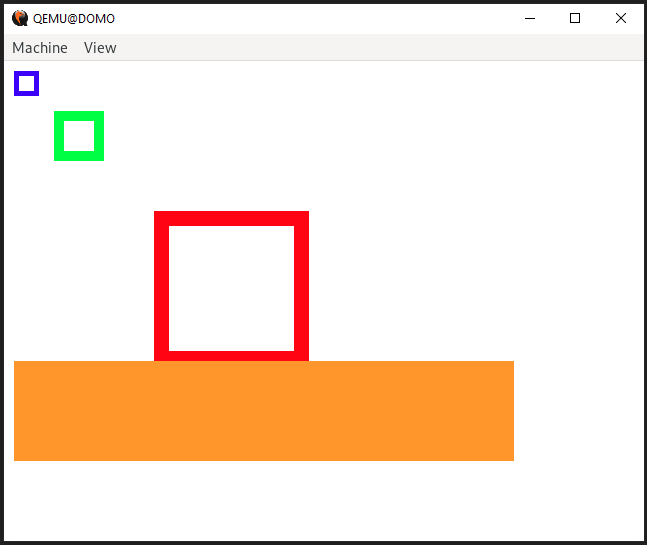
Testing
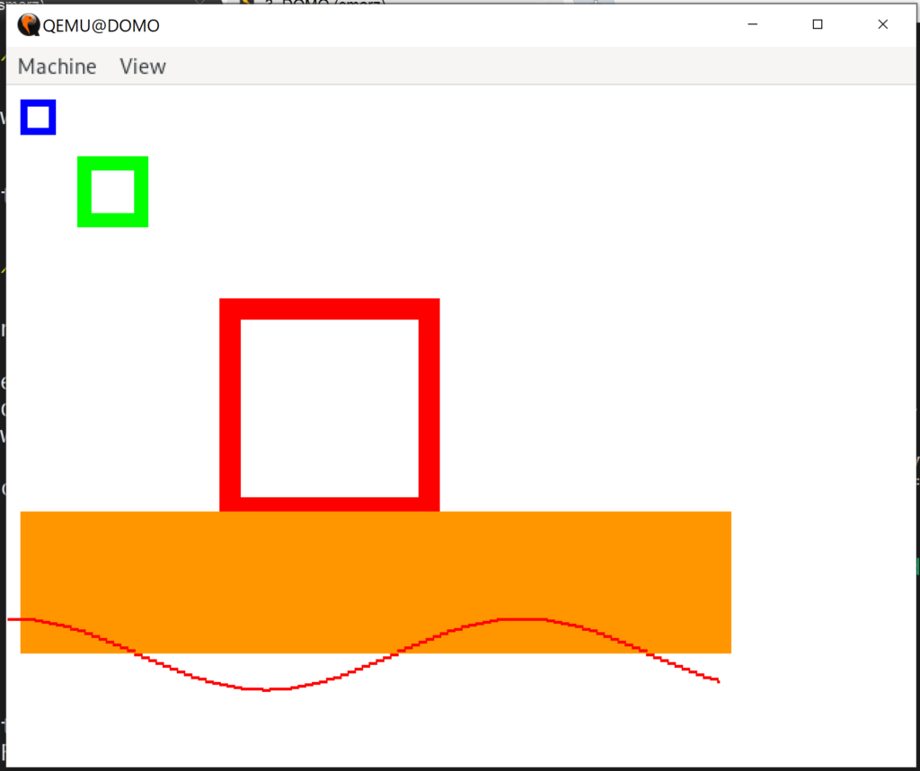
Now, the fun part. Let’s see if this works! Here’s our userspace code.
Let’s add in our cosine function and see what happens!
void draw_cosine(Pixel *fb, u32 x, u32 y, u32 width, u32 height, Pixel &color) {
   for (u32 i = 0; i < width;i++) {
      f64 fy = -cos(i % 360);
      f64 yy = fy / 2.0 * height;
      u32 nx = x + i;
      u32 ny = yy + y;
      fill_rect(fb, nx, ny, 2, 2, color);
      }
}
That’s looking good.
Conclusion
Our operating system is starting to look more and more like a normal operating system. We still need an input system so that we can interact with our operating system, but that’ll be the next thing we tackle.
Sometime in the future, we will compile newlib so that we have a standard library in userspace. Right now, we’re forced to write our own functions.