Contents
Repository
This blog series refers to the code written here: https://github.com/sgmarz/riscv_msi.
The APLIC specification (still in draft) is part of the Advanced Interrupt Architecture (AIA) specification, and it is kept here: https://github.com/riscv/riscv-aia.
I am using AIA specification version 0.3.0-draft.31 to write this article.
Introduction
The advanced platform level interrupt controller (APLIC) is an advanced version of SiFive’s PLIC. The main advancement is that it supports sending interrupts via message. So, when paired with an incoming MSI controller (IMSIC), the APLIC can send messages just like any other hardware device.
The main purpose of the original PLIC was to aggregate, prioritize, and send hardware interrupt signals. It provided a method for an operating system to claim, handle, and complete an interrupt request. The PLIC sent a notification to a specific HART (hardware thread — pretty much a CPU core) through an “external interrupt” pin. That HART would then determine what interrupted it by reading from a specific PLIC register called the claim register. This would return a number identifying the device. Usually, this number is a specific wire connecting a hardware device to the PLIC.
The Advanced Platform Level Interrupt Controller (APLIC)
The new APLIC is not backwards compatible with the SiFive PLIC. Some of the concepts and features are the same, but the register file and mappings are different. Technically, a system may be implemented without a full APLIC, but the AIA documentation specifically states that “[f]ull conformance to the Advanced Interrupt Architecture requires the APLIC.”
First, the APLIC registers are laid out as follows:
struct Aplic {
    pub domaincfg: u32,           // Domain CSR that controls how this APLIC functions
    pub sourcecfg: [u32; 1023],   // Source configuration for 1023 interrupts
    _reserved1: [u8; 0xBC0],

    pub mmsiaddrcfg: u32,         // Machine-level MSI address (for APLIC to write MSIs)
    pub mmsiaddrcfgh: u32,
    pub smsiaddrcfg: u32,         // Supervisor-level MSI address
    pub smsiaddrcfgh: u32,
    _reserved2: [u8; 0x30],

    pub setip: [u32; 32],         // Bitset to set pending interrupts (32 IRQS per element)
    _reserved3: [u8; 92],

    pub setipnum: u32,            // Sets a pending interrupt by number
    _reserved4: [u8; 0x20],

    pub clrip: [u32; 32],         // Bitset to clear pending interrupts (opposite of setip)
    _reserved5: [u8; 92],

    pub clripnum: u32,            // Clears a pending interrupt by number
    _reserved6: [u8; 32],

    pub setie: [u32; 32],         // Bitset to enable interrupts
    _reserved7: [u8; 92],

    pub setienum: u32,            // Enable an interrupt by number
    _reserved8: [u8; 32],

    pub clrie: [u32; 32],         // Bitset to disable interrupts (opposite of setie)
    _reserved9: [u8; 92],

    pub clrienum: u32,            // Disable an interrupt by number
    _reserved10: [u8; 32],

    pub setipnum_le: u32,         // Set an interrupt pending by number always little end first
    pub setipnum_be: u32,         // Set an interrupt pending by number always big end first
    _reserved11: [u8; 4088],

    pub genmsi: u32,              // Used to generate MSIs
    pub target: [u32; 1023],      // Target control per interrupt
}
Domain Configuration Register (domaincfg)

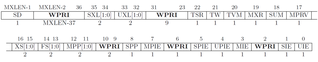
There are three usable fields in this register, interrupt enable (IE, bit 8), delivery mode (DM, bit 2), and big endian (BE, bit 0).
The first 8 bits is a byte order mark for all intents and purposes. It is set to 0x80 so that we can test to see whether the register is big end first or little end first. For example, if we instruct a “load word” (lw instruction in RISC-V), and we get 0x80 in the first byte, that means the machine is in big endian. If we don’t, it is little endian, and that byte we loaded contains the delivery mode and big-endian bits.
The interrupt enable bit enables the APLIC to send interrupts (1 = enabled, 0 = disabled). This doesn’t mean that the interrupt will necessarily be heard, but instead, it only means the APLIC can send interrupts by triggering a pending bit.
The delivery mode bit allows the APLIC to be configured to send normal interrupts, like the old PLIC, or to send interrupts as messages (MSIs). If the DM bit is set to 0, it will send direct interrupts, like the old APLIC. If the DM bit is set to 1, it will send MSIs instead.
The big endian bit allows the APLIC to write in big endian (BE = 1) or to write messages in little endian (BE = 0). However, the BE bit also affects the order of the multibyte domain configuration register too. The most significant byte is set to 0x80 on purpose to act as sort of a byte order mark.
We can configure a Rust function to set the domain register. All fields in this register are Boolean (yes/no, true/false, 1/0).
impl Aplic {
    pub fn set_domaincfg(&mut self, bigendian: bool, msimode: bool, enabled: bool) {
        // Rust library assures that converting a bool into u32 will use
        // 1 for true and 0 for false
        let enabled = u32::from(enabled);
        let msimode = u32::from(msimode);
        let bigendian = u32::from(bigendian);
        self.domaincfg = (enabled << 8) | (msimode << 2) | bigendian;
    }
}
Source Configuration Registers (sourcecfg[u32; 1023])

There is one sourcecfg register for every interrupt possible. Recall that interrupt 0 is not possible, so interrupt 1’s source configuration register is in sourcecfg[0]. This is why the example Rust code I provided subtracts 1 from the interrupt source’s value.
The delegate bit (bit 10) can be read to determine if the given interrupt has been delegated. This bit is read/write. If we write a 1 into this field, it delegates it to a child domain. If that particular source does not have a child domain, this bit will always be read 0.
The source mode bits (bits 2:0) control how the interrupt is triggered for those interrupts not delegated. If an interrupt is delegated (D=1), the bits 9:0 describe the index of the child it was delegated to. If the interrupt is not delegated (D=0), then each interrupt source may be configured to trigger a “pending” interrupt by one of the following.
| 3-bit “SM” value | Register Name | Description |
|---|---|---|
| 0 | Inactive | The interrupt source cannot generate an interrupt and is inactive. |
| 1 | Detached | The interrupt can only be generated by writing directly to the APLIC. |
| 2, 3 | – | Reserved |
| 4 | Edge1 | The interrupt is asserted on a rising edge (from 0 to 1). |
| 5 | Edge0 | The interrupt is asserted on a falling edge (from 1 to 0). |
| 6 | Level1 | The interrupt is asserted when high (device IRQ pin is asserted). |
| 7 | Level0 | The interrupt is asserted when low (device IRQ pin is deasserted). |
An inactive interrupt source cannot generate an interrupt through the APLIC, and we cannot manually assert an interrupt by writing to the interrupt pending register. A detached interrupt source cannot be triggered by the device, however we can manually write to the MMIO APLIC registers to assert the interrupt.
#[repr(u32)]
enum SourceModes {
    Inactive = 0,
    Detached = 1,
    RisingEdge = 4,
    FallingEdge = 5,
    LevelHigh = 6,
    LevelLow = 7,
}
impl Aplic {
    pub fn set_sourcecfg(&mut self, irq: u32, mode: SourceModes) {
        assert!(irq > 0 && irq < 1024);
        self.sourcecfg[irq as usize - 1] = mode as u32;
    }

    pub fn sourcecfg_delegate(&mut self, irq: u32, child: u32) {
        assert!(irq > 0 && irq < 1024);
        self.sourcecfg[irq as usize - 1] = 1 << 10 | (child & 0x3ff);
    }
}
Set/Clear Pending/Enable Interrupt (setip/clrip) Registers
These registers control whether an interrupt is pending. The APLIC will set these bits itself whenever an enabled interrupt is triggered; however, we can manually set an interrupt as a pending interrupt.
These registers are unlike the IMSIC registers. There is a set of registers to set a pending interrupt and a set of registers to clear a pending interrupt.
The setipnum and clripnum registers function much the same way as the following Rust functions that use the setip/clrip registers.
impl Aplic
    pub fn set_ip(&mut self, irq: u32, pending: bool) {
        assert!(irq > 0 && irq < 1024);
        let irqidx = irq as usize / 32;
        let irqbit = irq as usize % 32;
        if pending {
            // self.setipnum = irq;
            self.setip[irqidx] = 1 << irqbit;
        } else {
            // self.clripnum = irq;
            self.clrip[irqidx] = 1 << irqbit;
        }
    }
}
The interrupt enable registers act much like the interrupt pending registers, except they allow the interrupts to be signaled. If an interrupt is NOT enabled, then that interrupt is masked and cannot be triggered.
impl Aplic {
    pub fn set_ie(&mut self, irq: u32, enabled: bool) {
        assert!(irq > 0 && irq < 1024);
        let irqidx = irq as usize / 32;
        let irqbit = irq as usize % 32;
        if enabled {
            // self.setienum = irq;
            self.setie[irqidx] = 1 << irqbit;
        } else {
            // self.clrienum = irq;
            self.clrie[irqidx] = 1 << irqbit;
        }
    }
}
Generate MSI Register (genmsi)

There are two read/write fields and one read-only field in the genmsi register. The genmsi register can be used to trigger an MSI write, even though writing directly to the IMSIC is more efficient.
The hart index is the HART that you want to send an MSI and the EIID (external interrupt identifier) is the value to write to the IMSIC. Usually the EIID is the same number as the interrupt you want to trigger.
Target Control Registers (target[u32; 1032])
The target control registers have two different forms based on how the APLIC is configured. If the APLIC is configured in direct delivery mode, then the register contains a HART index and a priority. Smaller priorities are higher, so 10 has a higher priority than 20.

impl Aplic {
    pub fn set_target_direct(&mut self, irq: u32, hart: u32, prio: u32) {
        assert!(irq > 0 && irq < 1024);
        self.target[irq as usize - 1] = (hart << 18) | (prio & 0xFF);
    }
}
In MSI delivery mode, the register contains a HART index, guest index, and external interrupt identifier (EIID).

impl Aplic {
    pub fn set_target_msi(&mut self, irq: u32, hart: u32, guest: u32, eiid: u32) {
        assert!(irq > 0 && irq < 1024);
        self.target[irq as usize - 1] = (hart << 18) | (guest << 12) | eiid;
    }
}
Interrupt Delivery Control
As I mentioned previously, the APLIC may be configured in MSI or direct mode. In MSI mode, the messages are handled by the incoming MSI controller (IMSIC); however, in direct mode, the APLIC itself will control interrupts. This is done through the interrupt delivery control (IDC) section of the APLIC.
For the virt machine on QEMU, the interrupt delivery control registers are memory mapped to 0x. The registers are laid out as follows.
| Offset | Size (bytes) | Register Name |
|---|---|---|
| 0 | 4 | idelivery |
| 4 | 4 | iforce |
| 8 | 4 | ithreshold |
| 24 | 4 | topi |
| 28 | 4 | claimi |
Each IDC is for an individual HART and is 32 bytes. Therefore, HART #0’s registers start at offset 0, HART #1’s registers start at offset 32, and so forth.
The idelivery register enables the APLIC’s direct delivery mode. If this register is set to 1, then the APLIC may deliver interrupts, otherwise, if this register is set to 0, then the APLIC does not deliver interrupts.

The iforce register forces the APLIC to deliver an interrupt #0. If we write 1 to this register and the APLIC’s interrupts are enabled, then this will signal an interrupt.

The ithreshold register sets the interrupt priority threshold for an interrupt to be heard. A threshold of 0 means that all interrupts can be heard. If the value is non-zero, then any interrupt priority of that value or higher are masked, and hence not heard. In this case, as with everything else, the lower the number, the higher the priority. Don’t let 0 fool you, it’s just a special value that unmasks all priorities. However, a threshold of 1 means all interrupts will be masked, whereas a threshold of 2 means that only priority 1 can be heard.

The topi register holds the interrupt number that is the highest priority and is enabled. The register is split into two pieces: bits 25:16 hold the interrupt number and bits 7:0 hold the interrupt priority.

The claimi register is the same as topi except that it signals that we are claiming the top interrupt. When we read from this register, the pending bit for the given register will be cleared to 0.
The OS on the repo that I made only uses the MSI delivery mode, since this delivery control is much like the old PLIC’s.
Conclusion
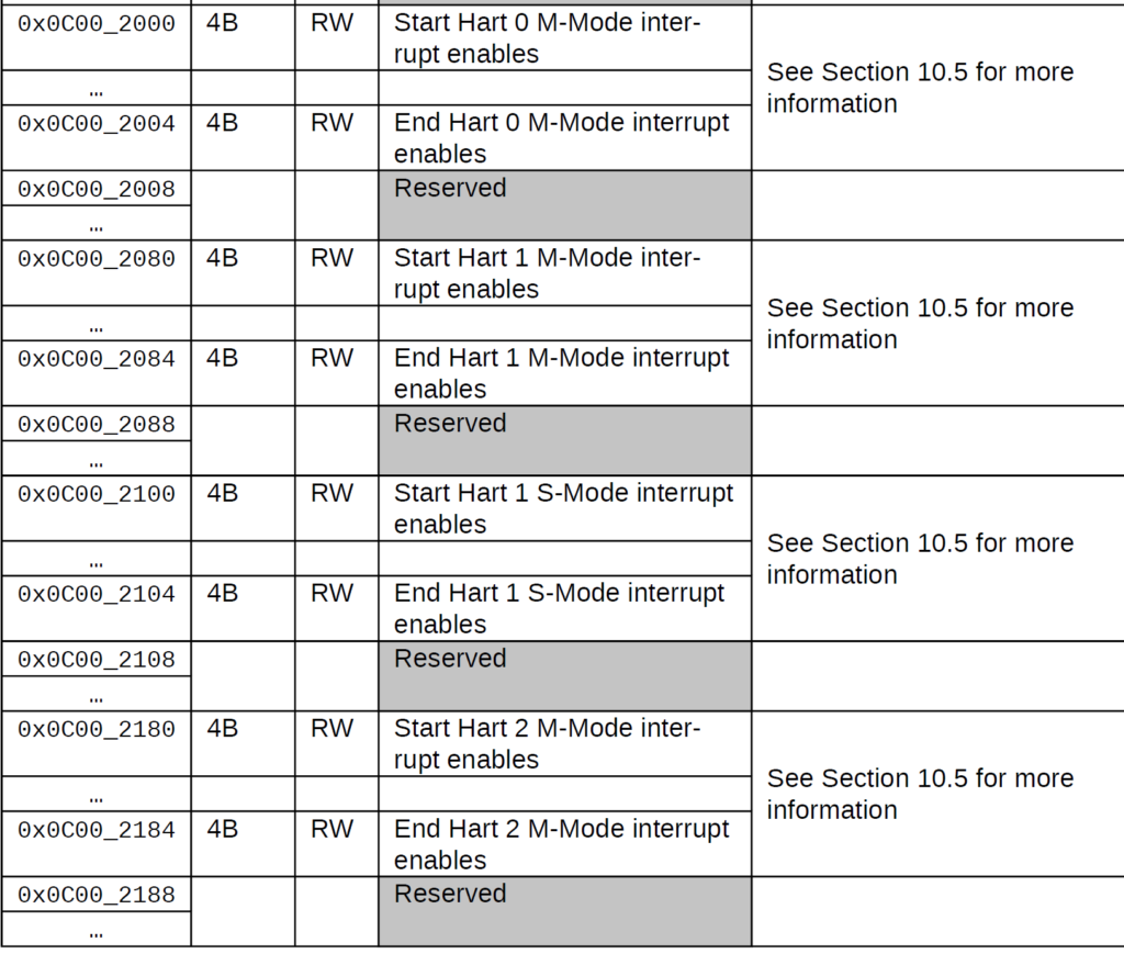
QEMU’s virt machine connects the UART to external IRQ #10, so we can use the APLIC to send messages whenever the UART receiver has data. This requires us to set up the APLIC using the registers above.
In the code below, I split between the machine and supervisor mode and delegate the UART to the supervisor APLIC (index 0).
pub fn aplic_init() {
    // The root APLIC
    let mplic = Aplic::as_mut(AplicMode::Machine);
    // The delgated child APLIC
    let splic = Aplic::as_mut(AplicMode::Supervisor);

    // Enable both the machine and supervisor PLICS
    mplic.set_domaincfg(false, true, true);
    splic.set_domaincfg(false, true, true);

    // Write messages to IMSIC_S
    mplic.set_msiaddr(AplicMode::Supervisor, crate::imsic::IMSIC_S);

    // Delegate interrupt 10 to child 0, which is APLIC_S
    // Interrupt 10 is the UART. So, whenever the UART receives something
    // into its receiver buffer register, it triggers an IRQ #10 to the APLIC.
    mplic.sourcecfg_delegate(10, 0);

    // The EIID is the value that is written to the MSI address
    // When we read TOPEI in IMSIC, it will give us the EIID if it
    // has been enabled.
    splic.set_target_msi(10, 0, 0, 10);

    // Level high means to trigger the message delivery when the IRQ is
    // asserted (high).
    splic.set_sourcecfg(10, SourceModes::LevelHigh);

    // The order is important. QEMU will not allow enabling of the IRQ
    // unless the source configuration is set properly.
    // mplic.set_irq(10, true);
    splic.set_ie(10, true);
}
We can now write the UART handler in the IMSIC whenever the UART sends interrupts.
pub fn imsic_handle(pm: PrivMode) {
let msgnum = imsic_pop(pm);
match msgnum {
0 => println!("Spurious 'no' message."),
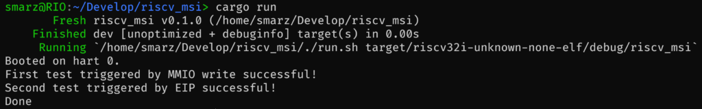
2 => println!("First test triggered by MMIO write successful!"),
4 => println!("Second test triggered by EIP successful!"),
10 => console_irq(),
_ => println!("Unknown msi #{}", msgnum),
}
}
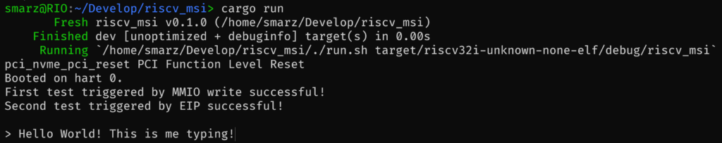
The code above forwards any message #10 to console_irq, which in turn pops a value off of the receiver buffer register of the UART device.
When all is said and done, we can start getting UART messages: